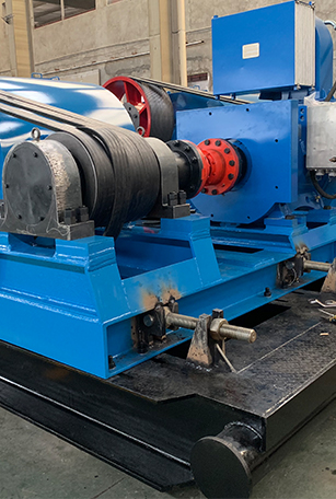


Gear Reducer is an independent component consisting of gear transmission, worm transmission and gear-worm transmission enclosed in a rigid case. It is often used as a deceleration transmission device between the original part and the working machine. It plays the role of matching speed and transferring torque between prime mover and worker or actuator, and is widely used in modern machinery.
We can do many kinds of type reducer, such as Lufkin type and so on.
Gear reducers include gears constructed using high alloy forged steel gear blanks, instead of standard cast steel. Gears are cut with 2-step process of rough cut - heat treat - finish cut, insuring deep penetration of heat treat process deep within gear tooth root. GB w/ forged steel gears carries a 5-year "no questions asked" warranty
Model | 25D | 40 | 57 | 80 | 114 | 160 | 228 | 320 | 456 | 640 | 912 | 1280 |
Whole machine parameters | ||||||||||||
T(IN·LBS) | 25000 | 40000 | 57000 | 80000 | 114000 | 160000 | 228000 | 320000 | 456000 | 640000 | 912000 | 1280000 |
Transmission ratio(i) | 31.6 | 33.12 | 30.25 | 31.832 | 28.355 | 28.506 | 28.873 | 28.807 | 28.255 | 28.363 | 28.79 | 28.68 |
L | 850 | 935 | 1037 | 1080 | 1330 | 1480 | 1610 | 1830 | 1920 | 2010 | 2317 | 2713 |
L1 | 165 | 180 | 200 | 225 | 250 | 300 | 350 | 370 | 400 | 400 | 440 | 550 |
L2 | 235 | 270 | 300 | 325 | 400 | 450 | 500 | 580 | 600 | 650 | 790 | 900 |
L3 | 305 | 340 | 376 | 382 | 474 | 498 | 550 | 632 | 670 | 710 | 832 | 913 |
H | 517 | 592 | 666 | 668 | 825 | 875 | 978 | 1142 | 1220 | 1267 | 1514 | 1675 |
H1 | 270 | 310 | 350 | 350 | 425 | 450 | 500 | 590 | 650 | 660 | 785 | 840 |
H2 | 30 | 30 | 30 | 42 | 40 | 40 | 55 | 60 | 60 | 60 | 60 | 60 |
Base mounting hole | ||||||||||||
A | 630 | 695 | 760 | 750 | 1050 | 1177 | 1334 | 1510 | 1580 | 1668 | 2002 | 2040 |
A1 | 260 | 300 | 330 | 300 | 350 | 430 | 430 | 460 | 450 | 545 | 700 | 355 |
A2 | 250 | 275 | 330 | 340 | 510 | 530 | 540 | 620 | 650 | 605 | 620 | 620 |
A3 | / | / | / | / | / | / | 155 | 185 | 250 | 285 | 380 | 160 |
A4 | / | / | / | / | / | / | 55 | 59 | 67 | 70 | 103 | 110 |
A5 | 60 | 60 | 50 | 48 | 65 | 72 | / | / | / | / | / | / |
A6 | 115 | 115 | 165 | 170 | 175 | 175 | 270 | 310 | 395 | 350 | 370 | 310 |
A7 | / | / | / | / | / | / | / | / | / | / | / | 590 |
B | 420 | 470 | 460 | 510 | 700 | 750 | 780 | 880 | 1000 | 960 | 1375 | |
B1 | 360 | 400 | 396 | 450 | 635 | 670 | 680 | 770 | 900 | 860 | 890 | 1235 |
n-d1 | 6-Φ22 | 6-Φ24.5 | 6-Φ23 | 6-Φ24.5 | 6-Φ32 | 6-Φ32 | 8-Φ35 | 8-Φ39 | 8-Φ48 | 8-Φ48 | 8-Φ48 | 10-Φ50 |
Input parameters | ||||||||||||
d | 200 | 200 | 250 | 250 | 300 | 300 | 300 | 400 | 400 | 400 | 500 | 600 |
Brake type | B | B | B | B | A | A | A | A | A | A | A | A |
h | 165 | 165 | 185 | 185 | 230 | 230 | 230 | 280 | 280 | 280 | 335 | 405 |
h1 | 150 | 150 | 165 | 165 | 215 | 215 | 215 | 265 | 265 | 265 | 315 | 380 |
h2 | 165 | 165 | 185 | 185 | 185 | 185 | 185 | 235 | 235 | 235 | 290 | 355 |
l1 | 250 | 250 | 250 | 250 | 290 | 290 | 290 | 290 | 290 | 290 | 290 | 460 |
l2 | 145 | 145 | 144 | 144 | 110 | 110 | 110 | 110 | 110 | 110 | 110 | 130 |
d2 | 474.4 | 474.4 | 616.6 | 616.6 | 772.16 | 772.16 | 925.16 | 1027.16 | 1127.76 | 925.16 | 1280.16 | 1280.16 |
W1 | 296 | 324 | 314 | 343 | 387 | 427 | 445 | 521 | 605.5 | 585.5 | 626 | 855 |
W2 | 256 | 286.5 | 283 | 308 | 355 | 395 | 407.7 | 472.5 | 575.7 | 542.5 | 595.2 | 795 |
W3 | 42 | 61 | 80 | 80 | 85.7 | 111 | 111 | 136.5 | 136.5 | 162 | 187.3 | 187.3 |
Pulley groove | 2B | 3B | 4B | 4B | 3C | 4C | 4C | 5C | 5C | 6C | 7C | 7C |
Output parameters | ||||||||||||
W | 986 | 1066 | 1092 | 1170 | 1500 | 1640 | 1744 | 1920 | 2230 | 2189 | 2280 | 2905 |
C1 | 108 | 118 | 138 | 135 | 197.5 | 192 | 212 | 210 | 240 | 240 | 235 | 260 |
C2 | 105 | 113 | 135 | 135 | 190 | 188 | 205 | 205 | 235 | 235 | 230 | 255 |
Axle End Type | A | B | B | B | A | A | A | A | A | A | A | A |
D | 80 | 90 | 90 | 90 | 130 | 150 | 175 | 175 | 200 | 200 | 200 | 230 |
P | / | / | 50 | 45 | 60 | 60 | 70 | 70 | 110 | 110 | 110 | 110 |
M | / | / | 1/2" | 5/8" | 3/4" | 5/8" | 3/4" | 3/4" | 3/4" | 1" | 1" | 7/8" |
t | 71 | 79 | 81 | 81 | 119 | 138 | 160 | 160 | 185 | 185 | 185 | 210 |
b | 22 | 25 | 25 | 25 | 32 | 36 | 45 | 45 | 45 | 45 | 45 | 56 |
Wedge key① | C22×18×105 | C25×20×110 | C25×14×135 | C25×16×135 | B32×18.5×170 | C36×20.5×185 | C45×25.5×200 | C45×25.5×200 | C45×38.5×230 | C45×38.5×230 | C45×38.5×230 | C56×32×255 |
Note:①Wedge angle1:100. | ||||||||||||
Leakage-proof machine type
Model | FSL9 | FSL13 | FSL18 | FSL26 | FSL37 | FSL53 |
Parameter | ||||||
T(KN·M) | 9 | 13 | 18 | 26 | 37 | 53 |
Transmission ratio(i | 46.7 | 46.526 | 41.43 | 44.386 | 45.83 | 41.2 |
L | 1200 | 1265 | 1303 | 1475 | 1625 | 1945 |
L1 | 250 | 260 | 250 | 300 | 350 | 400 |
L2 | 350 | 378 | 400 | 450 | 500 | 600 |
L3 | 410 | 435 | 448 | 495 | 590 | 660 |
H | 738 | 781 | 834 | 910 | 1081 | 1170 |
H1 | 380 | 410 | 450 | 480 | 560 | 600 |
H2 | 45 | 38 | 40 | 50 | 47 | 50 |
Base mounting hole | ||||||
A | 845 | 900 | 940 | 1140 | 1230/920① | 1500 |
A1 | 360 | 400 | 410 | 500 | 400/150① | 510 |
A2 | 360 | 400 | 230 | 250 | 325 | 420 |
A3 | / | / | 180 | 250 | 325 | 420 |
A4 | / | / | 60 | 70 | 65 | 75 |
A5 | 55 | 50 | / | / | / | / |
A6 | 180 | 200 | 230 | 250 | 325 | 420 |
A7 | / | / | / | / | / | / |
B | 510 | 580 | 600 | 720 | 900 | 920 |
B1 | 450 | 510 | 520 | 620 | 770 | 830 |
n-d1 | 6-Φ26 | 6-Φ26 | 8-Φ33 | 8-Φ33 | 8-Φ33 | 8-Φ33 |
Input parameters | ||||||
d | 250 | 300 | 300 | 300 | 300 | 400 |
Brake type | A | A | A | A | A | A |
h | 205 | 230 | 230 | 230 | 230 | 280 |
h1 | 190 | 215 | 215 | 215 | 215 | 265 |
h2 | 160 | 185 | 185 | 185 | 185 | 235 |
l1 | 325 | 360 | 290 | 360 | 365 | 310 |
l2 | 110 | 110 | 110 | 110 | 110 | 110 |
d2 | 660 | 760 | 750 | 912 | 1050 | 1120 |
W1 | 349 | 385 | 395 | 452 | 470 | 563 |
W2 | 317 | 342.5 | 368 | 410 | 436 | 508 |
W3 | 65 | 85 | 85 | 100 | 100 | 117.5 |
Pulley groove | 3B | 4B | 4B | 5-15N/J | 5-15N/J | 6-15N/J |
Output parameters | ||||||
W | 1190 | 1300 | 1434 | 1570 | 1670 | 1840 |
C1 | 135 | 170 | 180 | 195 | 195 | 220 |
C2 | 135 | 170 | 177 | 190 | 195 | 220 |
Axle End Type | B | B | B | B | B | B |
D | 90 | 110 | 125 | 155 | 175 | 180 |
P | 45 | 50 | 60 | 70 | 90 | 100 |
M | M16 | M16 | M16 | M20 | M20 | M20 |
t | 81 | 100 | 114 | 142 | 155 | 160 |
b | 25 | 28 | 32 | 40 | 45 | 45 |
Wedge key② | C25×16×135 | C28×21×170 | C32×22×177 | C40×30×190 | C45×37×195 | C45×40×210 |
Note:①Different Sizes of Left and Right Sides of Base Installation Plate for FSL37;②Wedge angle1:100;③Other models of our company also adopt some or all anti-seepage technology.。 | ||||||
0531-69959201
lqg18653457231
+86-18653457231
No 12111,Jingshi Road, Lixia District, Jinan City, Shandong Province. P.R. China

Professional customer service team, professional after-sale services create a comprehensive high-quality, advanced technology, reliable products, which gives you a strong sense of security.

Professionals, professional skills and precision equipments insure that we can provide you with professional product customization service.

The best quality products, strict quality control system and good reputations established Saigao product's irreplaceable place.

Superb technical team with continuous technological innovation, closely follow the market's trend help you to create the highest performance products.
 English
  日本語
日本語  français
  Español
  русский
  português
  العربية
  tiếng việt
  ไทย
ไทย  Polska
  română

